Perforation track display settings
Settings for each of the tracks and logs available in the selected template can be defined on the right side of the form in the Settings pane.
Track settings
When a track item in the structure window is clicked the settings related to track display appear in the Settings pane.
Track name A name for the track can be given in this field. The active track item in the Structure window will take the name given here.
Width The display width of the track. The default measurement is pixels (px), however, you can right-click the px designation and choose from centimeters, inches, millimeters or points.
Background Color The background color that will be applied only to the active track.
Gridlines Controls the visibility of gridlines for the selected track.
Grid color If gridlines are turned on you can select their color.
Marker names Controls the visibility of marker names for the selected track.
Align marker names Controls the positioning of the marker names within the track.
Curve filling settings
The curve filling settings allow you to customize a fill color and behavior for the logs in a track. You can create fill settings, for example, that fill between track edge and curve, between two curves or between a curve and a value. You can create as many fill settings as desired; these settings can then be managed by arranging the order in which they are applied and by indicating which settings are active.
A toolbar is available for managing your settings, including adding, deleting, and changing the order of the settings:

|
Add a new fill setting to the track. See the Fill Settings table below for details on creating a fill setting for your template. |

|
Change the order in which the settings are applied to the track. To change the position of a specific setting in the order, click the setting to make it active (the setting item will turn blue), then click the up or down arrow to change its position. |

|
Delete the selected setting. To delete a setting, click the setting to make it active (the setting item will turn blue), then click the delete icon. |
Fill settings
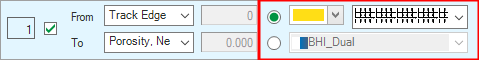
When you add a setting to the list with the button in the toolbar, a new, blank setting appears. Here you can specify the fill behavior that will be applied to the curves in the track. The following options are available for each setting:
 The assigned order of the setting. This is read-only. If you wish to adjust the order that the setting is applied, use the arrows as described under Curve Filling Settings above.
 Indicates whether or not the setting is active; checked boxes indicate active settings.
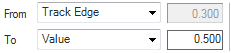
Fill behavior There are a few combinations you can define between the available fill types: Track Edge, Continuous, Value and Mean. Selecting Value activates the adjacent text boxes, where you can specify a value. Selecting Mean will shade the curves from a mean value to the track edge, another mean or log. For normal logs, the arithmetic mean is used. For logarithmic displayed logs, the geometric mean is used.
Fill color Select either a solid color or a colorset to use for the fill setting.
Perforation settings
Select the perforation item under the perforations track. The related settings appear in the Settings pane.
Perforation name A name for the perforations can be given in this field. The active track item will also take the name given here.
Alignment Select how to align the perforation in the perforation track. Choose between left, full width or right.
Fill Displays the perforations in the schematic track when On is selected. Select Off to hide the perforations in the well schematic track.
Fill color Select a color to display the perforations (if Fill is toggled on) in the perforation track.